Vijeo Designer Basic 1.1
Vijeo Designer Basic 1.1 for the Magelis GXU series HMIGXU3500 HMIGXU3512 HMIGXU5500 HMIGXU5512 product range
Vijeo Designer Basic Configuration
A. Introduction of Vijeo Designer Basic
Vijeo Designer Basic is software that functions to design (Buildtime), download, and simulate the application of a Human Machine Interface (HMI) system, while for running programs (runtime) already included in the HMI. But if you use Personal Computer (PC) or iPC (Industrial PC) as its running program, runtime is needed. For Vijeo Designer Basic, there is no runtime available on PC, only in Vijeo Designer Version 6.x.Vijeo Designer Basic for the Magelis GXU series products, including:
HMIGXU3500: 7 "(800x480) basic model, 1 serial port, including RTC
HMIGXU3512: 7 "(800x480) universal model, 2 serial ports, 1 Ethernet port, including RTC
HMIGXU5500: 10.1 "(800x480) basic model, 1 serial port, including RTC
HMIGXU5512: 10.1 "(800x480) universal model, 2 serial ports, 1 Ethernet port, included
RTC
To operate Vijeo Designer Basic you must have the software installer which can be downloaded at:
System specifications for Vijeo Designer basic:
| Specification | Vijeo Designer Basic Editor |
| The platform | PC |
| The CPU | Pentium 4 - 2 GHz or more |
| Memory | 1GB minimum, 2GB or more |
| Disk | 2.0 GB or more |
Operation System | Microsoft Windows XP Professional (Service Pack 3 or above) |
| Microsoft Windows 7 32 and 64 bit |
| Microsoft Windows 8.1 32 and 64 bit |
| Web browser | Microsoft Internet Explorer 6.0 (recommended version 7 or above) |
User Interface
- 1. Toolbars (Access all menus needed) 2. Menubar and tools needed to develop HMI applications)
- Navigator (Create and access all elements in the application such as panels, pop up windows, java scripts, alarms, variables etc.)
- Inspector (Display Properties of selected items)
- Feedback Zone (displays an error message and shows the progress of the validation, build, and download process, press F4 or double click on the error message, it will jump to the location of the error)
- ToolChest (Display the tools used on the panel)
- Graphic Editor (Design, create, edit displays, variables, panels, etc.)
A. Introduction to Vijeo Designer Basic
In practice this time, the HMI to be used is the HMIGXU3512 type (7 inch wide HMI, Universal model, 2 serial ports, 1 Ethernet port) which will be connected to the M221 PLC.After installing the application, follow the steps below.
A. Configuring Vijeo Designer Basic
1. Open the Vijeo Designer Basic Shortcut on the Desktop or Start Window
2. Then the display will open as below, to create a new program select Creat
New Project then select Next.
- Creat New Project (Creating a new project / program)
- Open Last Project (Open the last opened project)
- Open Existing Project (Open a project that was saved in a file with the format .smbp)
3. Create a project name: 'Pump1' in "Project Name", then click next
4. On the "target type" select HMIGXU Series, then on the model select HMIGXU 3512x, then click next
5. For the IP address, adjust it as shown below, then click next 
- IP Address (target IP Address or HMI to be downloaded)
- Subnet Mask (the target Subnet Mask or HMI to be downloaded)
- Default Gateway (IP Address gateway needs to be filled in if this HMI is connected to other networks)
6. The following display is for selecting Devices from various brands / Manufacturers available at
Vijeo Designer Basic software. The device to be used is the Schneider brand, then select
"Schneider Electric Industries SAS". After that select the Driver / protocol that is "Modbus TCP / IP",
then on the equipment select "Modbus Equipment", then click ok and then click finish.
7. Display User Interface
B. Vijeo Designer BasicSimulation In Vijeo Designer Basic simulation the basic thing needed is to create variables, new panels, and graphics (lamp / output, switch / input).For example:Creating a simple program to run a Pump using the on-off pushbuttonfollows the steps.1. Equipment Configuration Before creating variables, it is necessary to configure the equipment (device / PLC) that is used first .
In the "Navigator" column select modbusEquipmennt, then fill in IP Address: 127.0.0.1 (IP Simulator = PC as device / PLC), check the IEC61131 Syntax box if checked then the format of the HMI address is to use% Mxx). Then select OK.
2. Creating Variables First determine the input and output variables Input: Pushbutton ON, =% M1 Pushbutton OFF =% M2 Output: Pump =% M3 See the following picture, in the Navigator select "Variables", then on the right bar sheet select "New Variable "
Create a new Variable as follows
1st Variable:
in column 1. Variable Name fill: PB_ON
2. Data Type select: BOOL
3. Data Source select: External
4. ScanGroup select: ModbusEquipment01
5. Device Address contents:% M1
Information :
1> Variable Name = The variable used
2> Data Type = The data type matches the device address
3> Data Source = External means data used from other devices
4> ScanGroup = Select the device to use
5> Device address = Address used for one variable
2nd Variable:
in column 1. Variable Name fill: PB_OFF
2. Data Type select: BOOL
3. Data Source select: External
4. ScanGroup select: ModbusEquipment01
5. Device Address contents:% M2
3rd Variable:
in column 1. Variable Name fill: PUMP
2. Data Type select: BOOL
3. Data Source select: External
4. ScanGroup select: ModbusEquipment01
5. Device Address contents:% M3
If the variable has been created, then the Graphic Editor will appear as follows.
3. Make a Chart
Graphic List: List of objects in the current panel Graphic List: List of objects in the current panel
7. In the next screen, click ModbusEquipment at the bottom left 8. Then the display will appear as shown below, then check the column "
simulated without using hardware, then click ok
9. Then right-click on the "Variables" tab, then click "link variables", then select the program file that has been saved on SoMachine
11. In the next screen, check the address that we will use on the HMI as shown below, then click add.
12. Then click "Panel1" for us to design the HMI display we want. Examples of HMI displays in accordance with the SoMachine program that have been made are below.


 1.1 Use of SoMachine
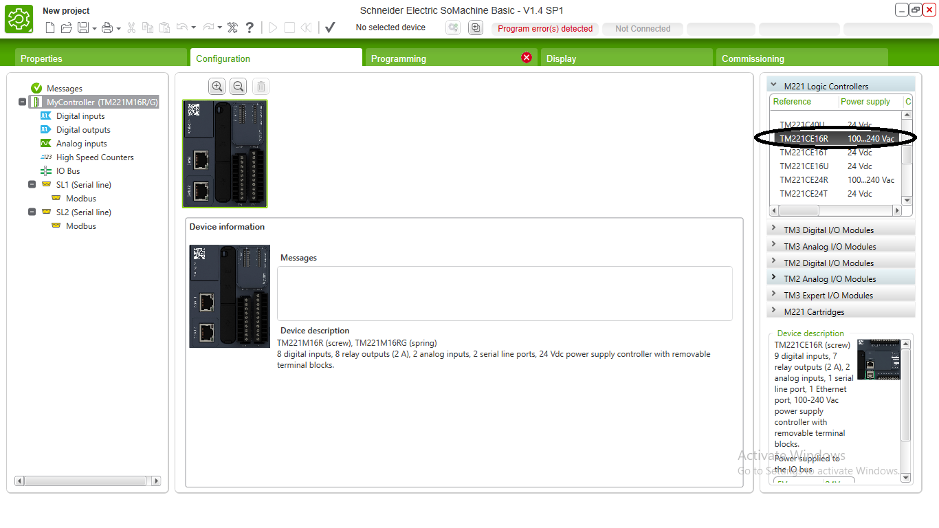
 4. Still in the configuration tab, on the left, in the ETH1 section we will change the fixed ip address according to the picture below, then click "apply"
 5. After that we can make a program as we want on the "programming" tab, and the image below is an example of a simple program on the PLC circuit